
24V vs 48V Low-Voltage Track Systems: Voltage Drop, Cable Sizing and Long-Run Design
1.Why 24V and 48V behave differently
This guide lets a project team make three early decisions: select the voltage platform, choose a feed topology and screen a preliminary conductor size before detailed product verification.
A low-voltage track system looks simple—one DC source, two conductors and movable luminaires—but long routes and high fixture counts make current and resistance decisive. For the same connected power, a 24V branch draws twice the current of a 48V branch. With the same route and conductor, 48V therefore produces roughly half the absolute voltage drop and about one-quarter of the percentage drop.
That relationship is not a universal instruction to specify 48V. Short 24V branches, centre feeds and modest loads can perform well. The controlling criterion is whether every luminaire stays within its permitted input range under the worst credible operating condition, while conductor ampacity, protective devices, thermal limits, controls and local installation rules are also satisfied.
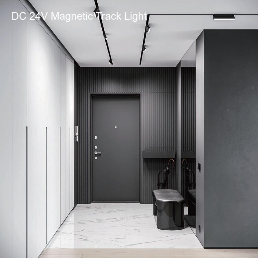
A 24V magnetic track lighting application; circuit length, connected load and feed position determine voltage-drop performance.
2. Voltage-drop calculation method
For a first-pass calculation, use rated input power divided by nominal system voltage: I = P / Vnom. For constant-power electronic loads near the end of a high-resistance branch, current rises as the actual luminaire input voltage falls. Recalculate using the actual input voltage—by iteration or an exact constant-power model—or use the manufacturer's maximum input current. The luminaire's permitted input-voltage range remains the final acceptance limit.
For a two-wire DC circuit with a load concentrated at the far end, the following provides a conservative cable-only upper bound:
Vdrop = 2 × L × I × R / 1000 | I = P / Vnom | Ploss = I² × (2LR/1000) |
L is one-way length in metres, I is branch current in amperes and R is conductor resistance in ohms per kilometre. The factor 2 covers outgoing and return conductors. Track rails, adaptors, joints, polarity devices and feed connectors add resistance, and copper resistance increases with temperature. Include those allowances before declaring compliance.
3. 24V vs 48V: a like-for-like comparison
Assumptions: 100W total load; 30m one-way route; 2.5mm² IEC Class 1/2 copper at 20°C; 7.41Ω/km maximum DC resistance; all load treated as end-loaded; cable only; nominal-current first pass.
System | Current | Cable drop | Drop % | Design consequence |
24V / 100W | 4.17A | 1.85V | 7.7% | Normally divide the branch, shorten the run, centre-feed or increase conductor size. |
48V / 100W | 2.08A | 0.93V | 1.9% | Often workable at first pass, subject to track, connector, temperature and input-range checks. |
The electrical advantage of 48V becomes most useful where a project wants longer branches or fewer feed points. The 24V result is not a product failure; it indicates that the proposed route and loading need a different topology.
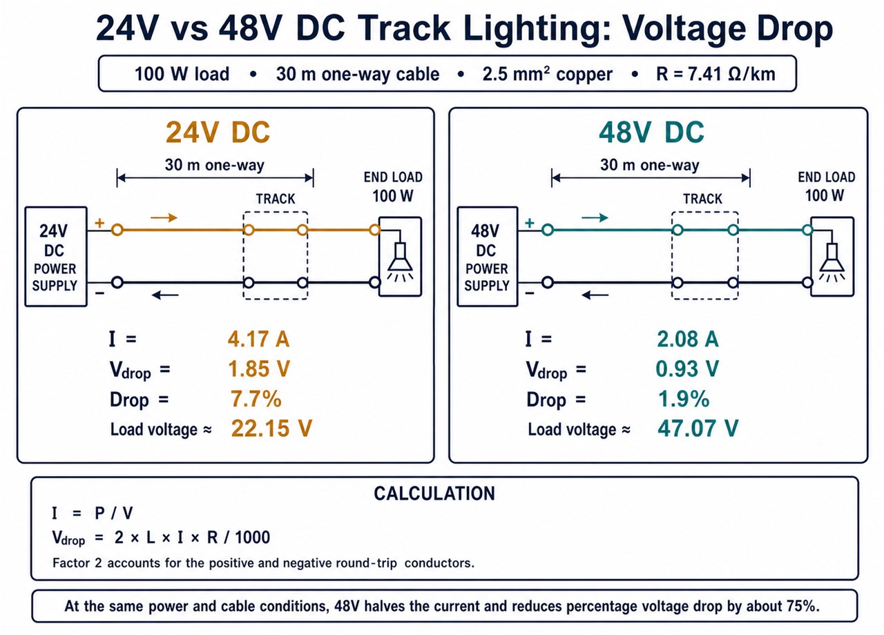
End-loaded cable-only comparison at 100W, 30m one-way and 2.5mm² copper; product input limits and added system resistance still require verification.
4. Worked example: 40m retail track
Assumptions: twelve 8W fixtures (96W); 40m one-way route; 2.5mm² Class 1/2 copper at 20°C; end-loaded cable-only upper bound; nominal-current first pass; no connector or track allowance.
At 24V, current is 4.0A and calculated cable drop is 2.37V, or 9.9%. At 48V, current is 2.0A and drop is 1.19V, or 2.5%. Against the project-defined DC-branch voltage-drop allowance, the 48V result must still leave sufficient margin for track, connector, source-tolerance and temperature effects, while the 24V end-feed requires redesign.
A centre feed creates two 20m halves with about 48W on each side. The cable-only first pass falls to approximately 0.59V (2.5%) at 24V and 0.30V (0.6%) at 48V. This illustrates why feed location can be more effective than simply increasing cable size.
5. Distributed loads and movable fixtures
Track luminaires are distributed, so each conductor segment carries only the current of fixtures downstream. A segment-by-segment model is therefore more representative than placing the whole load at the far end: calculate each segment's drop as 2 × length × downstream current × resistance / 1000, then sum the segments to each fixture position.
The end-loaded calculation is still valuable as an upper bound, especially before a final fixture schedule exists. During detailed design, test the actual layout and at least one credible future arrangement with luminaires moved toward the remote end. Keep a fixture schedule that records position, rated power, maximum input current and permitted input voltage.
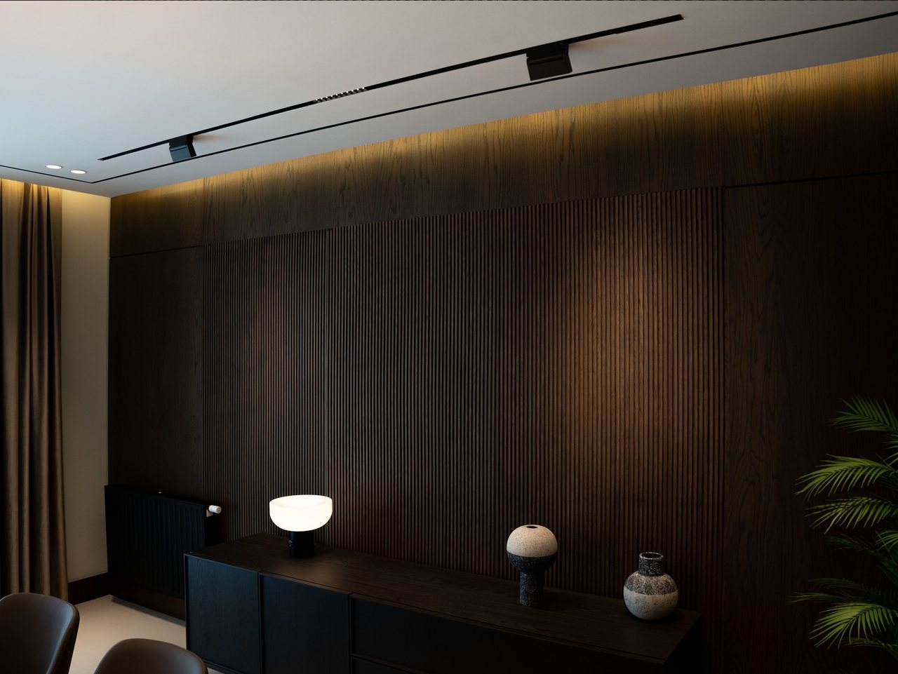
Distributed magnetic track luminaires along a continuous ceiling run; actual load positions affect downstream current in each segment.
6. Cable sizing: resistance is only the first check
The values below are maximum DC resistance at 20°C for common IEC 60228 Class 1/2 copper conductors, not generic values for every cable construction. Flexible Class 5/6 conductors and manufacturer-specific cables may differ; use the applicable datasheet for final design.
Copper area | Approx. AWG | Max. DC resistance at 20°C |
1.5mm² | 15 | 12.1Ω/km |
2.5mm² | 13 | 7.41Ω/km |
4mm² | 11 | 4.61Ω/km |
6mm² | 9 | 3.08Ω/km |
For a screening temperature correction, Rθ ≈ R20[1 + 0.00393(θ − 20)] for copper. Final selection must also verify ampacity, bundling and ambient derating, protective-device coordination, short-circuit withstand, termination capacity, polarity, insulation rating, voltage-drop allowance and local code requirements. A larger conductor that does not fit the feed terminal is not a valid design.
7. Feed topology and circuit division
When voltage drop is excessive, change the current path before defaulting to oversized conductors. Common measures are centre-feeding, feeding from both ends only when the product architecture permits it, dividing the track into shorter protected branches, moving the power supply closer to the load or choosing 48V for a higher-power long run.
Example—60m distributed run. Assumptions: twenty 12W fixtures, evenly spaced every 3m; 48V nominal; 2.5mm² Class 1/2 copper at 20°C; cable only. Treating all 240W as end-loaded gives an upper bound of 4.45V (9.3%). A segment-by-segment nominal-current calculation gives about 2.33V (4.9%). Dividing the route into three approximately 20m, 80W branches reduces each branch's end-loaded cable-only upper bound to about 0.49V (1.0%), before other allowances.
Do not parallel power supplies or create multiple feeds unless the system manufacturer explicitly permits the arrangement and defines isolation, polarity and protection. Feed topology is part of the system architecture, not just a wiring shortcut.
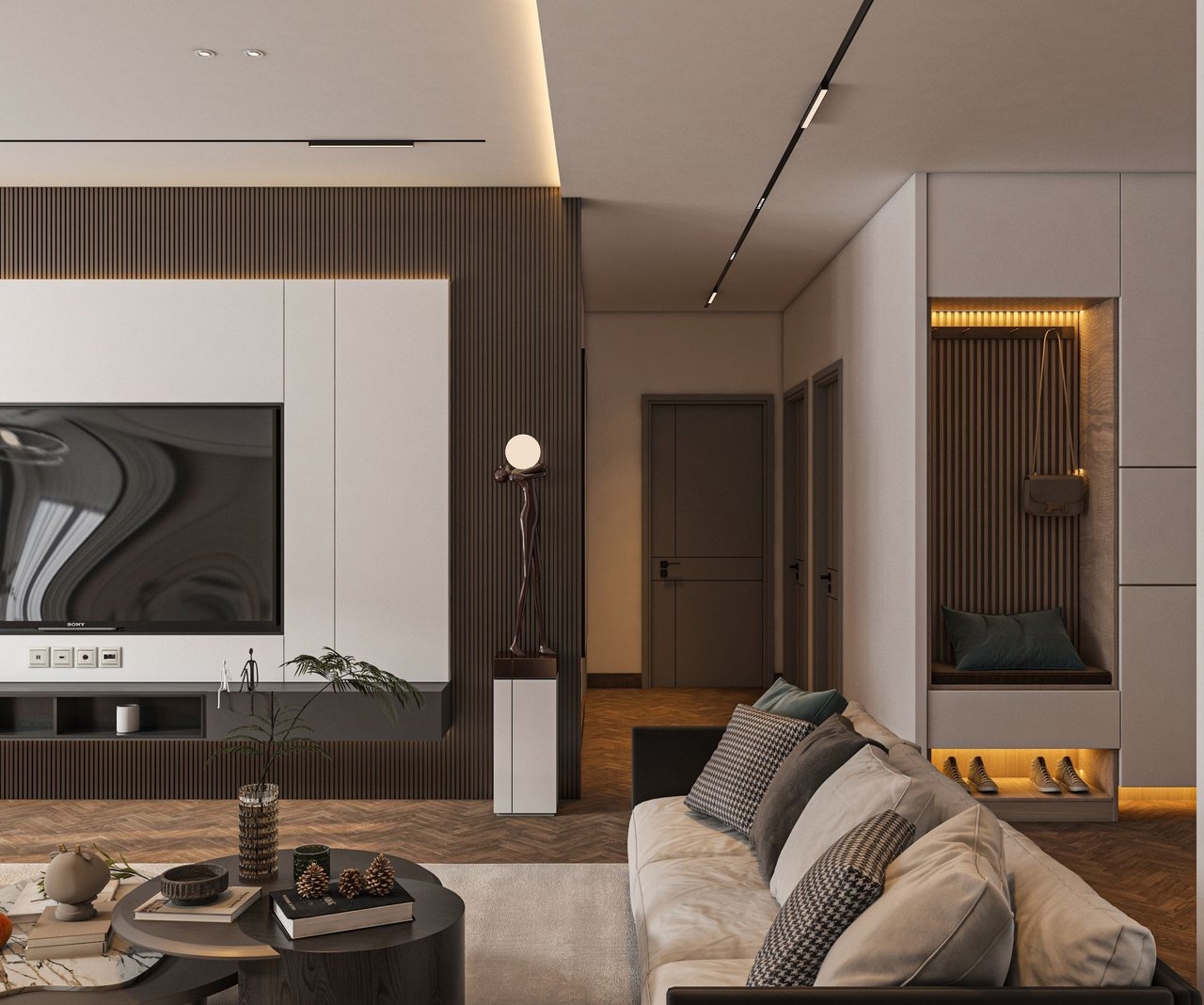
Multiple track runs in one interior should be assigned to a documented branch, feed and protection plan.
8. Project selection framework
Project condition | Initial direction | Checks before release |
Short run, modest load, local driver | 24V may be practical | Remote input voltage, terminal rating, controls and expansion margin |
Long run or high connected power | Evaluate 48V and divided feeds | Worst-case layout, temperature, connector/track resistance and protection |
Frequent fixture relocation | Use distributed-load plus end-loaded checks | Approved adaptor range, polarity, commissioning record |
Tight ceiling/service access | Reduce feed count only if calculations allow | Driver location, heat, isolation and maintenance access |
Mixed controls or multiple luminaire types | Freeze the system compatibility matrix | Voltage, current, dimming protocol, driver and mechanical interface |
A useful preliminary worksheet needs: system voltage, source tolerance, fixture quantity and power, maximum input current, permitted input range, one-way segment lengths, conductor class and resistance, track and connector allowance, ambient temperature, feed position, protective device and spare capacity. Record assumptions beside each result so later revisions remain auditable.
9. Applying the method to ANOVA magnetic track systems
ANOVA's 24V/48V DC low-voltage centralized lighting system range can be assessed with the same branch method. Relevant fixture families include the 24V magnetic track spotlight, 24V magnetic flood linear light and 48V linear magnetic track light. Use the selected models' actual electrical limits; do not mix products merely because they share a nominal voltage.
For importers and project teams, a single project window can coordinate product selection, branch schedules, multi-SKU supply, assembly/QC, regional document checks and final BOM compatibility. This reduces handoffs without replacing the project electrical engineer. Freeze the approved track, adaptor, luminaire, power-supply and control combination before procurement.
Project-coordination example. The Hanoi custom retail lighting project demonstrates a BOQ-to-installation workflow: checking fixture schedules against ceiling and display conditions, reviewing illuminance in DIALux, coordinating mounting, wiring and drivers, and following installation through final visual checks. For long-run track projects, review branch layout, feeds, drivers, controls and commissioning as one coordinated package.
10. Installation and commissioning checks
1.Confirm the power supply output setting, polarity, protective device and branch identification before energising.
2.Record source voltage and the voltage at the electrically most remote luminaire under the intended maximum load.
3.Compare measured drop with the design calculation; investigate unexpected differences at feeds, joints, adaptors and track sections.
4.Verify luminaire operation at minimum expected source voltage and maximum credible load, including dimming and control states.
5.Thermally inspect accessible terminations after stabilisation where project procedures permit, then retain the load schedule and readings for maintenance.
Commissioning evidence should state instrument, load state, ambient condition, measurement points and date. Without those details, a photograph of a voltmeter is not a reproducible validation record.
11. Standards and verification references
IEC 60364-5-52:2009+A1:2024 addresses selection and erection of wiring systems; Clause 525 and the relevant annex cover installation voltage drop. IEC 60364-4-41:2005+A1:2017 covers protection against electric shock, including the project context for SELV/PELV measures. IEC 60228:2023 defines conductor sizes and resistance requirements.
ETSI TR 103 229 V1.1.1 (2014-07), Annex A is cited only for RI and RI² calculation principles; it is not a certification standard for magnetic track systems. Apply the current editions and local rules adopted by the project jurisdiction.
12. Frequently asked questions
Is 48V always better than 24V for track lighting?
No. At the same power, 48V lowers current and percentage voltage drop, but 24V can be suitable for short, centre-fed or lightly loaded branches. Compare both against the actual luminaire input range, controls, topology and project constraints.
Can cable cross-section alone solve voltage drop?
Not always. A larger conductor reduces cable resistance, but branch length, feed position, distributed load, track resistance, connections, protection and terminal capacity may control the result. Splitting or centre-feeding often gives a cleaner design.
Should voltage drop be calculated to the end of the track?
Calculate to the actual fixture positions. Treating the full load as end-loaded is a useful upper bound. Once the layout is known, use segment-by-segment downstream current and test a plausible relocation case.
What voltage-drop limit should be used for a low-voltage track branch?
Use the limit required by the project standard and local wiring rules, then confirm that the most remote luminaire remains within its permitted input range under minimum source voltage and worst-case load. The acceptance limit should be stated in the project criteria and applied consistently to cable, track, connections, source tolerance and temperature allowances.
How should connector and track resistance be included?
Add documented resistance for track conductors, feeds, joints and adaptors to the cable calculation. Where published values are not available during concept design, reserve a stated allowance and verify the completed branch by measuring source and remote-fixture voltage under the intended maximum load.
Request a technical system review
For a preliminary discussion, provide the track layout, one-way segment lengths, fixture schedule, intended voltage, control method, power-supply location, conductor details and project country. Subject to the information supplied and the agreed scope, the discussion may cover:
a voltage-platform recommendation with stated assumptions;
a preliminary branch/load and voltage-drop review;
feed-location and circuit-division comments; and
compatibility and BOM flags for the proposed system combination.
Submit the project through the ANOVA contact form or email sales@anovalighting.com. Final electrical design and code compliance remain the responsibility of the qualified project professional.