
DALI-2 Track Zone Troubleshooting: Addresses, Outputs and Groups
If two DALI-2 track zones dim together, the wrong section responds, or a scene recalls the wrong white tone, do not replace the driver first. Start by finding where the project’s logical control map stops matching the physical installation. Check four places in order: the short address, group or scene data, controller targeting, and the connection between each control function and the intended track load.
This guide gives commissioning technicians and lighting contractors a repeatable way to isolate that mismatch. It also explains why an output terminal, DALI address, group and zone name are not interchangeable.
Quick diagnosis
| Observed symptom | Layers to check | First test |
| Two zones work separately from direct address tests but move together from a wall control | Group membership, controller targeting or duplicate addressing | Check the button or application action, target group and broadcast use; if address identification is ambiguous, rule out duplicate short addresses before editing groups |
| One individual address always changes two track sections | Duplicate short addresses, logical-unit mapping or a shared physical output | Rule out duplicate short addresses, then trace the logical-unit-to-output mapping and both track feeds. |
| Brightness is correct but a scene recalls the wrong white tone | Stored DT8 scene data or later override | Compare direct colour commands with scene recall and monitor subsequent commands |
| The correct response appears briefly, then changes | Automation or another application controller | Temporarily observe or suspend scheduled and sensor-driven actions |
Separate the logical map from the physical installation
First identify the project's control architecture. In a centralized-output architecture, DALI controls a central driver or controller, so zoning depends on its addressable output functions and on how each track load is mapped to those outputs. In a luminaire-level architecture, each luminaire or track adapter contains addressable control gear; multiple luminaires can share the same mains supply and DALI bus while remaining independently controllable by short address or group. Independent DALI control therefore does not require a separate power circuit for every zone.
The logical layer determines which control gear receives a command and which stored behavior it applies. A short address identifies a control-gear logical unit on one DALI line. Groups allow several units to receive the same command, while scenes store recallable settings in each participating unit.
The physical layer determines where the electrical output goes. It includes the driver, output function, terminals, cables, track feeds and connected luminaires. A label such as "East Display" in commissioning software does not prove that the corresponding track section has a separate electrical feed.
DALI is specified by the IEC 62386 series. General control-gear requirements are published in IEC 62386-102:2022 (Edition 3.0). For the commissioning model used here, see the DALI Alliance Quick Start Guide v1.1 (April 2023), sections 4.1 and 4.2: one DALI subnet supports up to 64 control-gear addresses, while control gear can be assigned to 16 groups and store 16 scenes. A group number is not an output-channel number, and a scene number is not a zone address.
DALI-2 certification confirms that a product has passed the applicable certification process; it does not validate a project's zone schedule or wiring. The DALI-2 and DALI version-1 comparison also explains that DALI-2 extends standardized coverage to control devices such as application controllers and input devices.
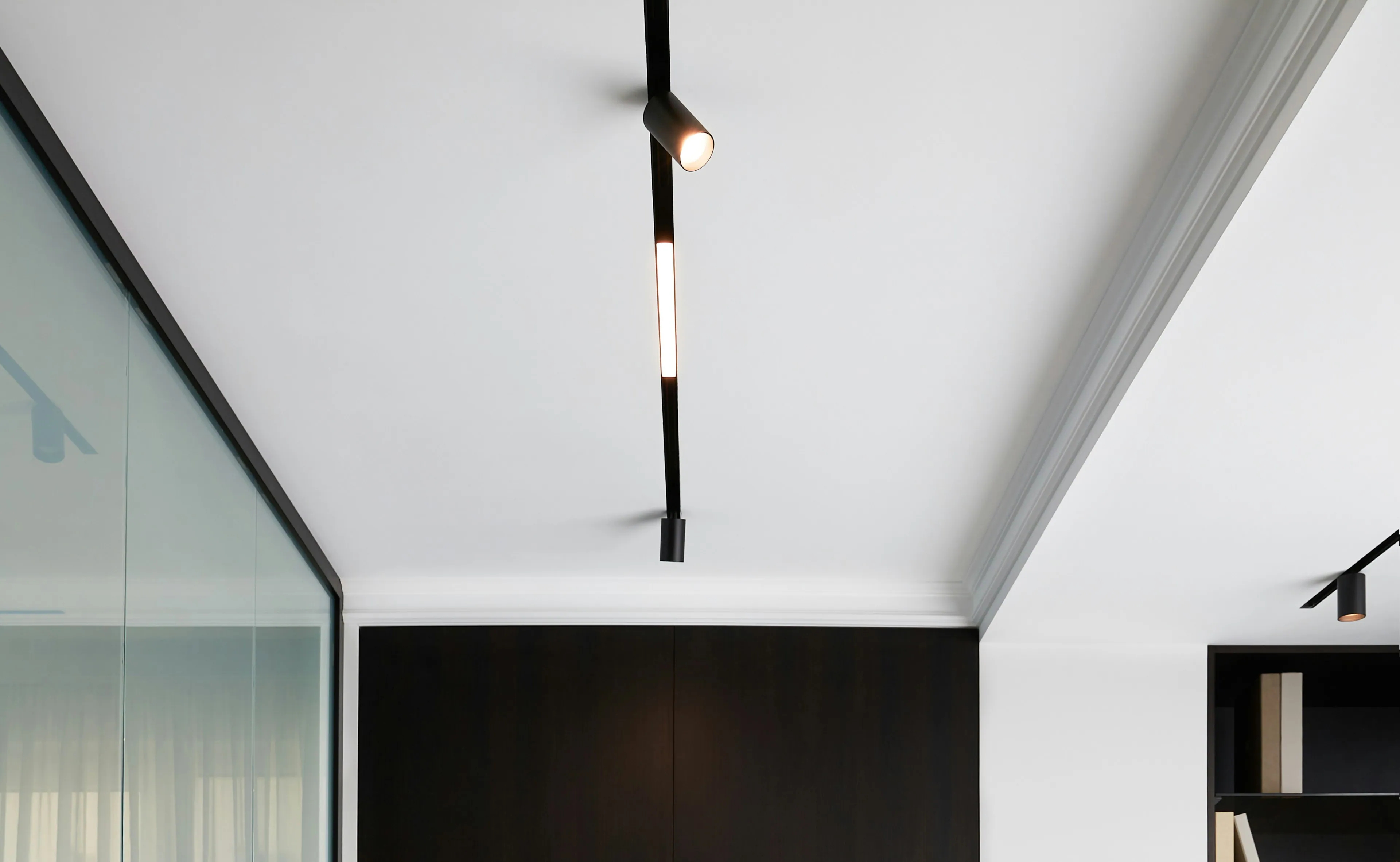
Track-lighting interior. Photo by Marina Nazina on Unsplash; cropped for editorial use.
Do not derive address count from terminal count
A multichannel driver can have several output terminals without presenting one independently addressable lighting zone per terminal. Some products expose multiple logical units; others coordinate outputs within one colour-control function. The product documentation and commissioned inventory must show which logical unit controls which output function.
Likewise, luminaires cannot become independently controllable merely by creating more software groups when they are connected to one commonly controlled output. Separate behavior requires enough addressable control functions and a load mapping that lets those functions act on the intended luminaires. In a luminaire-level architecture, that separation can exist in the control gear at each luminaire even when the luminaires share a power circuit.
Use this distinction as an early fork in the diagnosis. If two sections respond independently to individual-address commands but move together from the wall control, investigate group membership or controller targeting. If one individual-address command always changes both sections, trace the logical-unit mapping and physical output before editing groups.
Use this seven step diagnostic sequence
Use commissioning software, a handheld configurator or a suitable USB to DALI interface. Export or record the existing configuration before changing anything. Change one variable at a time, because each test result should eliminate a specific fault layer.
1.Reproduce and define the fault. Record the initiating button, sensor event, software command or scene recall. Note the expected response, actual response, affected luminaires, brightness, colour and timing. A wrong response that occurs immediately is different from a correct response that is overridden seconds later.
2.Map every responding luminaire. Mark all expected and unexpected responders on the layout. Compare the pattern with both the intended zone names and the physical track feeds. Do not assume adjacent track sections share a driver, or that sections in different rooms have separate feeds.
3.Identify each control gear address. Read the installed inventory and compare it with the approved schedule. Identify each address using a visible level change, then record the actual load that responds. Investigate missing units, unexpected logical units and suspected duplicate addressing with the tool manufacturer's procedure. Avoid reset or reinitialisation commands at this stage until the tool and device documentation confirms exactly which address, group, scene, controller or project data the command will clear.
4.Verify groups and scenes. Read group memberships from the installed gear where the tool supports it instead of trusting only an offline project file. Test each intended group. Then recall the affected scene first to a known individual address and then to the intended group. Compare stored levels and supported colour settings.
5.Trace the output and track feed. Follow each identified logical unit to the driver output function, terminal, cable, feed and track section. Compare terminal labels with the installation drawing. A qualified electrical professional should isolate and verify the relevant circuits before connections or continuity tests are changed.
6.Test normal controls and automation. If direct commissioning commands work, repeat the test from the normal button, sensor or application. Check the selected DALI line, destination address or group, scene number, broadcast commands and event-to-action assignment. Observe scheduled actions and other application controllers that may send a later command.
7.Correct one cause and retest. Apply the smallest correction supported by the tests. Repeat the original failing action, neighboring-zone controls, scene recall and any relevant sensor sequence. Update the as-built mapping only after the result matches the control intent.
Illustrative diagnostic example — not a documented project case
| Check | Expected result | Actual result | Conclusion and next action |
| Send an individual-address command to address 12 | Only the east display track responds | Only the east display track responds | Address 12 and its physical load mapping are consistent |
| Send an individual-address command to address 13 | Only the west display track responds | Only the west display track responds | Address 13 and its physical load mapping are consistent |
| Press the wall control labelled East Display | Only address 12 responds | Addresses 12 and 13 respond together | Based on these observations, first investigate controller targeting or group data. If address-identification results are inconsistent, rule out duplicate addressing before changing the track feeds |
| Read the target and installed group memberships | The control targets group 2; only address 12 belongs to group 2 | The control targets group 2; addresses 12 and 13 both belong to group 2 | Remove address 13 from group 2, save the configuration and repeat the original and neighbouring-zone tests |
Troubleshoot tunable white and RGBW scenes separately
Colour control for Device Type 8 is specified in IEC 62386-209:2011 (Edition 1.0), together with the applicable DALI-2 changes and certification test procedures. The DALI Alliance overview of DALI colour control distinguishes tunable-white colour type Tc, RGBWAF and xy colour control. A DT8 logical unit can coordinate several physical colour outputs through one short address, so those outputs may be colour components rather than separate zones.
When a scene recalls the correct brightness but the wrong correlated colour temperature, verify the addressed unit, supported colour type, stored scene colour and controller command sequence. A brightness-only test does not prove that colour commissioning is correct.
If direct colour commands work but one scene produces the wrong white tone, inspect that scene’s stored colour data and any command that follows the recall. If direct tests are also wrong, compare the driver configuration and warm/cool output connections with the approved wiring diagram.
Apply the same discipline to RGBW or RGBWAF installations. Confirm the supported colour type and the connection of each colour component. Do not assume that every DT8 product supports every colour-control method.
Build a commissioning record that survives product changes
Use a naming convention that preserves both the logical and physical identifiers. For example: "Line A / address 12 / driver D3 / output function TW / track T2 / east display." Keep the familiar zone name, but do not let it replace the identifiers needed for fault tracing.
The as-built record should connect the electrical drawing, control-gear inventory, logical-unit mapping, group memberships, scene intent and controller configuration. Record the expected brightness and colour response, the test action used for acceptance and the software numbering convention where it differs from the protocol values.
Keep one approved representative configuration as a golden sample, including its wiring diagram, configuration export and witnessed results. After a driver substitution, verify electrical compatibility, logical-unit count, device-type support, output functions and scene data. A similar terminal count does not prove that the replacement behaves the same way on the DALI line.
Connect the control brief to the lighting specification
Treat the control brief as part of the product specification. State the required DALI function, number of independently controlled zones, colour-control method, expected scene behavior and the mapping from each control function to each track feed. Confirm the selected product configuration and any required certification before order approval.
For multi-market projects, add region-specific constraints to the same mapping. In EU retail or hospitality work, record the emergency-lighting interface, local control intent and the conformity documents requested by the project team. For Middle East malls or luxury retail, also record the design ambient temperature, long-run voltage-drop assumptions and maintenance access. For Australia and Oceania projects, record the electrical and product-conformity documents requested by the project team, the local emergency-lighting interface requirements and any relevant site-exposure assumptions. These inputs support product selection but do not replace review against the applicable local codes and project specifications.
Frequently asked questions
Why do my DALI zones dim together?
First test the zones with individual-address commands. If they respond separately, check shared group membership, broadcast commands and controller targeting. If one address always changes both sections, investigate duplicate addressing, logical-unit mapping and a shared driver output or track feed.
What is the difference between a DALI address and a group?
A short address identifies a control-gear logical unit on one DALI line. A group lets several units receive the same command. Changing group membership changes who receives a group command; it does not change which physical load is connected to a driver output.
Does every driver output need a DALI address?
No. Address use depends on the product's logical architecture and operating mode. Some outputs can belong to separate logical units, while others work together as one colour-control function. Use the manufacturer's mapping and the commissioned device inventory.
Why does a DALI scene recall the wrong white tone?
The addressed gear may contain incorrect stored colour data, receive an incompatible command or be overridden by later application logic. Compare direct colour control with scene recall. If direct control is also wrong, check the supported colour mode, driver configuration and warm/cool connections.
Can DALI and DALI-2 devices be used together?
DALI-2 control gear is designed for backward compatibility, but legacy equipment does not gain newer DALI-2 features. Check older control gear, controllers and bus power supplies individually, and follow the DALI Alliance guidance for mixed systems.
Should I reset all DALI addresses to fix a wrong zone?
Not as the first step. Save the configuration and identify each address. Before using any reset, initialise or recommissioning command, check the tool and device documentation to confirm whether it clears control-gear short addresses, group and scene data, application-controller settings or the project database. A gear reset, address reassignment and controller factory reset have different scopes and recovery steps.
ANOVA Lighting product and configuration review
ANOVA Lighting was established in 2003 in Foshan, China, and provides ODM design and customized lighting services. Its published range includes track lights, downlights, LED modules, drivers and low-voltage lighting products.
For a project using low-voltage track lighting, review ANOVA's 24V and 48V centralized lighting system range and its overview of magnetic track lighting solutions. For mains track applications that require dimming options, the zoomable track light page lists DALI dimming among the available adapter configurations.
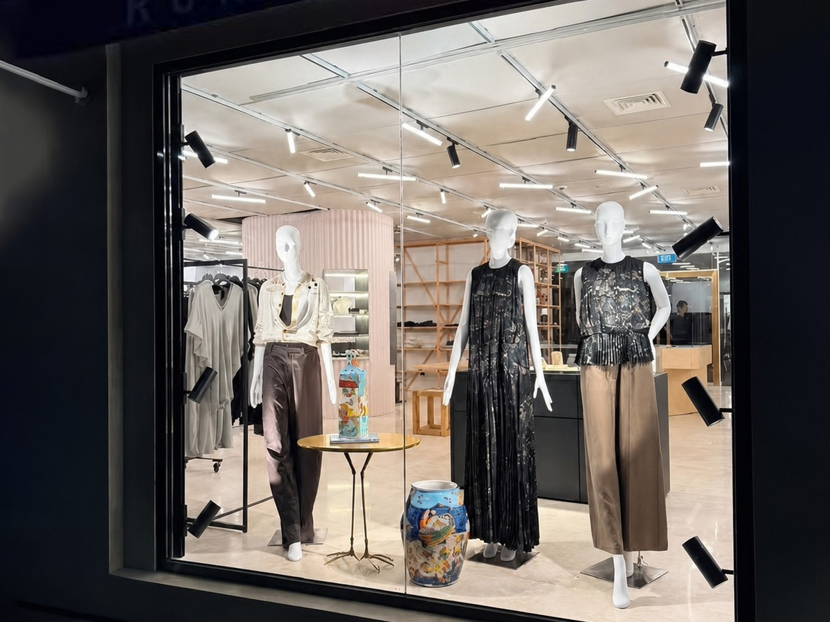
Request a DALI track configuration review
A useful enquiry includes the track layout, driver schedule, single-line or wiring diagram, required DALI functions and zone-control narrative. For an existing fault, also include the exported address list, group memberships, affected scene data, controller action and a marked-up plan showing which sections respond.
Ask ANOVA Lighting to confirm whether the proposed product configuration supports the required DALI functions, zone mapping and scene behaviour before quotation.
Send the project brief to sales@anovalighting.com or use the ANOVA Lighting contact page. Final circuit design, protection, installation and commissioning approval remain the responsibility of the project's qualified electrical professionals.